

How To Change Steering Box Vw Bus
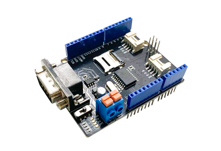
Tin can-Bus Shield V2.0
Can-BUS is a mutual industrial omnibus because of its long travel distance, medium advice speed and high reliability. It is normally constitute on modern car tools, such every bit an automotive diagnostic charabanc.
This CAN-Omnibus Shield adopts MCP2515 CAN Bus controller with SPI interface and MCP2551 CAN transceiver to requite your Arduino/Seeeduino Tin can-BUS adequacy. With an OBD-II converter cablevision added on and the OBD-II library imported, you lot are set to build an onboard diagnostic device or information logger.
Version
This document applies to the post-obit version of products:
| Version | Released Date | How to Purchase |
|---|---|---|
| CAN BUS Shield V1.0 | Oct 14, 2012 |  |
| CAN Jitney Shield V1.1 | Aug x, 2013 | |
| CAN Motorbus Shield V1.2 | January 5, 2015 | |
| CAN Motorcoach Shield V2.0 | Aug 01,2017 | |
What'south new in CAN BUS Shield V1.2
- Pads on the backside of PCBA
- Change terminal resistor to 120 Ohm
Alternative Choice
If your project is space limited and also don't demand other fuctions except Tin-BUS, hither is a Grove Tin can-BUS module which is Arduino compatible, more meaty and cost effective, delight click here to visit its folio.

What if I want to connect this shield to my auto
If you want to read data or control your car, there's an OBD>DB9 cablevision available for you, this cable make easier to connect to OBD-connector and DB9-connector. This cable will as well work with anything that has a OBD-connector. Add a power switch makes such a satisfying click.

USB-CAN Analyzer
If yous want a Tin Omnibus Analyzer to debug your Can Charabanc, this USB-Tin Analyzer is recommended.

Features
- Implements Can V2.0B speed up to i Mb/s
- SPI Interface speed up to 10 MHz
- Standard (11 bit) and extended (29 bit) data and remote frames
- Two receive buffers with prioritized message storage
- Industrial standard DB-9 connector
- LED indicators
Annotation
Tin BUS Shield Work well with Arduino UNO (ATmega328), Arduino Mega (ATmega1280/2560) as well as Arduino Leonardo (ATmega32U4).
Hardware Overview
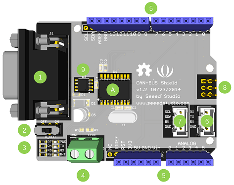
- DB9 Interface - to connect to OBDII Interface via a DBG-OBD Cable.
- V_OBD - It gets ability from OBDII Interface (from DB9)
- Led Indicator:
- PWR: power
- TX: glimmer when the data is sending
- RX: blink when there's information receiving
- INT: data interrupt
- Final - CAN_H and CAN_L
- Arduino UNO pivot out
- Series Grove connector
- I2C Grove connector
- ICSP pins
- IC - MCP2551, a high-speed CAN transceiver (datasheet)
- IC - MCP2515, stand-alone CAN controller with SPI interface (datasheet)
Alarm
When you use more than two CAN Bus Shield in one net, y'all should have the impedance into consideration. You lot should either cut P1 in the PCB with a pocketknife, or just remove R3 on the PCB.
Pin map
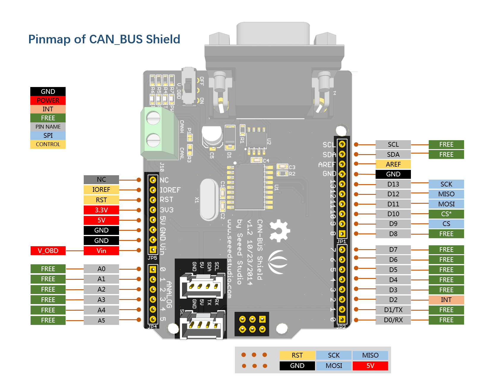
Note
The Free pin is bachelor for the other usages.
DB9&OBDii Interface

CS pin
Attention
When nosotros produced the new batch of CAN-Charabanc Shield V2, the wire of the back pads was embedded inside the PCB, although the wire betwixt the pads is now not visible on the exterior, the inside is all the same connected, if you want to change the wiring of the pads, you nonetheless need to cut the wiring in the PCB first.
SPI_CS pin of V1.2 is connected to D9 by default. If you want to change to D10, delight follow beneath instructions.
- Step1: Take a look at the backside of the PCBA, you lot will discover a pad named CS.
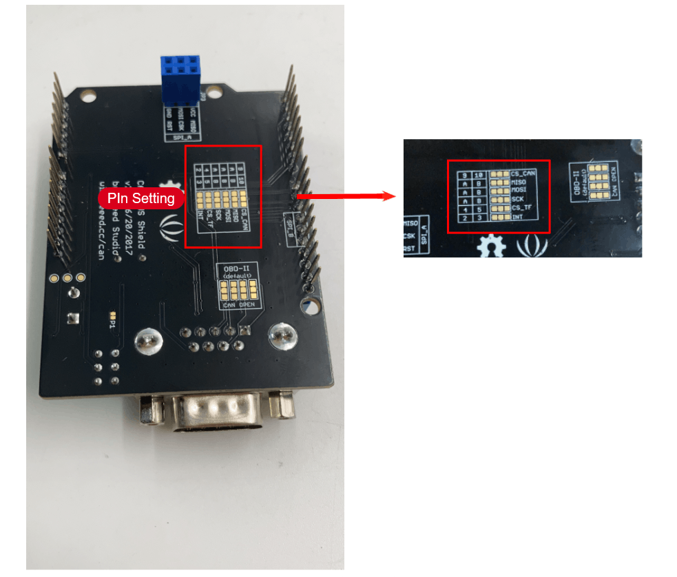
- Step2: Cut the wire betwixt pad9 and the center pad.

- Step3:Solder the middle pad and pad ten.

Alarm
Be conscientious with the box cutter, it's easy to hurt yourself or the PCBA.
SPI pins
The SPI pins (SCK, MISO, MOSI) are routed to the ICSP pins past default. But for some boards, the SPI pins are located at D11~D13. if this happens, you need brand some change to the PCBA. Accept a look at the backside of the PCBA, in that location're three pads, MOSI, MISO and SCK, they are continued to A past default. Y'all can alter them to B if needed.
Note
For Arduino UNO, Arduino Mega, Arduino Leonardo and any others AVR based Arduino boards, it works well by default setting.
Warning
Exist careful when you are going to alter SPI pins, information technology's easy to hurt yourself or the PCBA.
Getting Started
Here's a simple example to show you how Tin can-BUS Shield works. In this example we demand two pieces of CAN-BUS Shields as well every bit Arduino or Seeeduino.
STEP1: What do we need
| Proper name | Function | Qty | Link |
|---|---|---|---|
| CAN-BUS Shield | Tin Autobus communication | 2 | link |
| Seeeduino V4.2 | Controller | 2 | link |
| Jumper Wire | connection | 2 | link |
STEP2: Hardware Connectedness
Insert each Can-Coach Shield into Seeeduino V4.two, and connect the two Tin can-BUS Shield together via 2 jumper wires. Shown as beneath images.

Note
CAN_H to CAN_H, CAN_L to CAN_L
STEP3: Software
Delight follow how to install an arduino library procedures to install Tin can Omnibus shield library.
- Download the Seeed_Arduino_CAN Arduino library here.
Install the library to your Arduino IDE when it is downloaded.
I of the node (a node means Seeeduino + CAN_BUS Shield) acts equally master, the other acts as slaver. The master will send information to slaver constantly.
Note
Each node can deed as master earlier the code being uploaded.
Open up the transport example (File > Examples > Seeed_Arduino_CAN > send) and upload to the master.

Or copy the following to the Arduino IDE and upload:
#include <SPI.h> #include "mcp2515_can.h" /*SAMD core*/ #ifdef ARDUINO_SAMD_VARIANT_COMPLIANCE #ascertain SERIAL SerialUSB #else #define SERIAL Series
0 Response to "How To Change Steering Box Vw Bus"
Post a Comment